Data validation principles have been applied recently to a railways reverse-engineering project with great success. B and ProB have demonstrated again how efficient they are when used in combination.
This project was aimed at redeveloping an IDE for Embedded Diagnosis Systems (EDS), mostly from scratch as source code and development documentation are lost. Obsolete hardware (with no direct access to the filesystem) and original IDE were used for black box testing.
A huge collection of examples was designed and typed in, in order:
- to collect generated binary files,
- to guess the structure of the files,
- to determine the compilation rules, with the only support of the 68k assembly code of the target language interpreter, as the binary code and instructions are specific to this application.
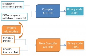
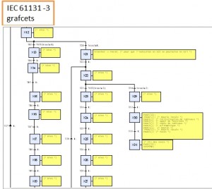
oreover the two inputs languages used by the original IDE, ancestor of hierachical grafcets and Pascal with French keywords, are old and not standardized. An extra step was to define two new languages, based on the IEC 61131-3 standard, that would be supported by the new IDE, and to provide means to import original programs into the new IDE.
The ultimate constraint was to be able to compile programs such as resulting binaries are bitwise identical to the ones obtained from the original IDE. Target application used for validation is around 800k bytes.
After several reverse-engineering, it appeared that the binary file was composed of several “components” such as grafcets, programs, procedures, etc. but without any symbol table and so no direct mean to detect which compilation order is required. In order to recover this order, it was decided to focus on the order of execution of grafcets and subgrafcets.
An EDS application consists in navigating into hierarchical grafcets: an active state of a grafcet can activate a subgrafcet (a child grafcet) as long as this state remains active. So from the program side, the relationships between the grafcets is known (parent-child relation is an acyclic directed graph). From the binary side, grafcet activation instructions can be parsed and are associated to a grafcet, such as another acyclic directed graph can be construsted. The main issue is that we don’t know easily how to associate grafcet state from one graph to binary code reference from the other graph, except for the root of the graphs. Each graph is made of 160+ nodes and would require a lot of computation to find the solution.
This problem was solved elegantly by using data validation principles: a B model representing the two graphs and their properties were elaborated, and ProB used for finding a solution.
From the grafcet modelling side, G7 represents the set of all grafcets appearing in the project
G7 = {main, G1, G2, G3, G4, …. }
and next is the relation associating to a grafcet its children.
next: G7 <-> G7
next = { …, G7 |-> G11, …}
From the binary file side, ADR represents the set of all entities (grafcet, program, etc.) appearing in the project (in fact their “address”)
ADR = {0x01, 0x13, 0x15, …}
and suiv is the relation associating to an entity the other entities that are called.
suiv: ADR <-> ADR
suiv = { … , 0x10 |-> 0x15, …}
The property that was searched was: “Sub-grafcets called in the binary file should comply with sub-grafcets activated in input models“. There exists a bijection bij that associates to a node of G7 a node of ADR such as children of both nodes match.
The property is expressed in B as follows:
bij: G7 >->> ADR &!xx.(xx: G7 => bij[next[{xx}]] = suiv[bij[{xx}]])
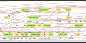
ProB managed to find the solution (in fact the two solutions … ) in less than 10 seconds. The resulting matching graph is:
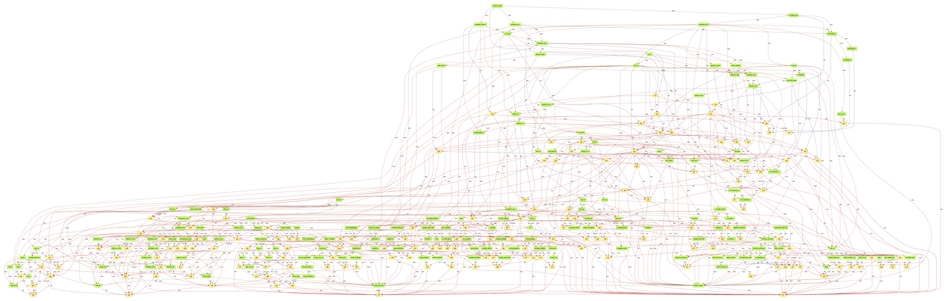
It finally appears that:
- the graphs are not acyclic (some loops exist that are real bugs)
- some sub-grafcets are declared but never activated (dead code)